
Problem overview: why low-load THD suddenly matters
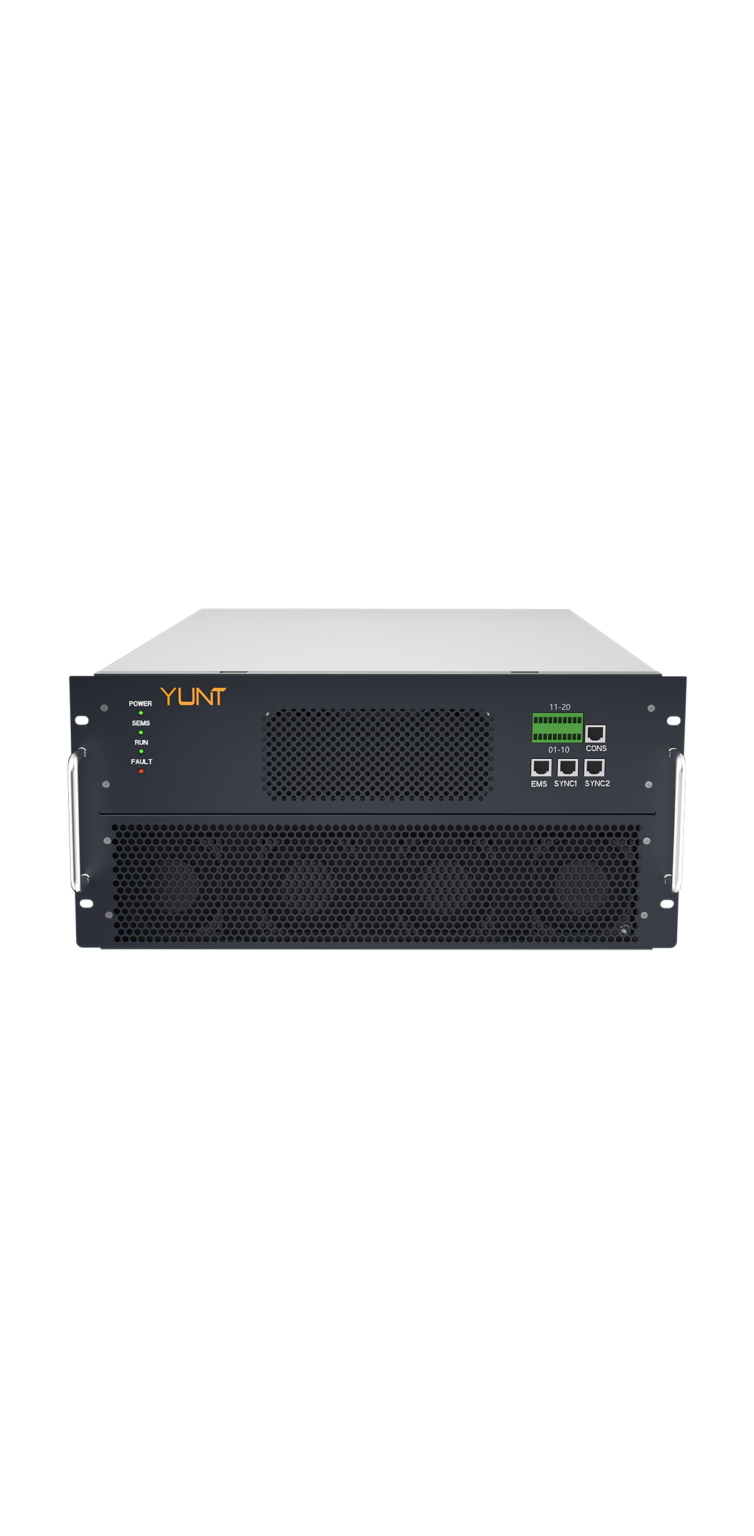
Many hybrid inverter installations behave fine at typical loads but start showing rising total harmonic distortion (THD) as they dip below manufacturer low-load thresholds. This is the specific problem field engineers face when switching between grid-tied and battery operation or when microgrid loads fall to standby levels. A careful inspection of the pcs module and its control firmware often reveals the root cause: control-loop interactions, PWM mode transitions, or inactive auxiliary circuitry that can’t maintain linear waveform shaping at low power.
Real-world anchor and the stakes
Past events such as the 2013 Typhoon Haiyan response showed how critical clean inverter output is during prolonged outages—improvised loads and generator-parallel systems exposed THD sensitivity under varied loading. The practical lesson is clear: THD spikes under low-load conditions can damage sensitive appliances and trip protective relays during disaster relief, so they’re not just technical quirks. Many grid codes and utility interconnection guides target THD under 5% for inverter output; when a hybrid inverter’s THD climbs above that at low load, it becomes an operational risk.
Diagnosis checklist: fast, repeatable steps
Start with scoped measurements—use a clamp and a true-RMS meter or a harmonic analyzer and document THD vs. load from 100% down to the lowest operational point. Log switching frequency, line voltage, and battery state-of-charge. Inspect the control firmware for low-load PWM modes and check whether the inverter’s active filtering is disabled below a threshold. Also review the power conversion modules topology: some modules enter discontinuous conduction or change modulation schemes, which alters harmonic content.
Common-root causes and what fixes look like
Typical culprits include: suboptimal dead-time calibration at low duty cycles, gain changes in the current loop that push the system toward instability, and unintended skipping of synchronous modulation. Fixes range from simple parameter tweaks—tightening current-loop bandwidth or adjusting dead-time compensation—to firmware updates that maintain continuous modulation or enable low-power active filtering. In multi-unit systems, asymmetric sharing can create harmonic beat frequencies; retuning droop and communication timing usually helps.
Operational production teardown: what engineers actually open up
In an operational production teardown you inspect the DC-link bus, gate-drive supply stability, EMI filters, and the CMS for firmware revision notes. Document where {main_keyword} appears in the signal path and flag any modules where {variation_keyword} is used as a fallback mode. Compare board-level component tolerances against the inverter’s spec sheet and test low-load behavior in isolation—no parallel gensets—so the true device signature is visible.

Alternatives and common mistakes
Some teams reflexively add passive LC filtering to hide THD without addressing control behavior—this can mask the problem but invites resonance with the grid or genset. Others oversize the inverter’s minimum continuous load, which wastes capacity and complicates management. Better options include coordinated firmware updates, adding a small, always-on resistive or active bleed to keep the converter in its linear range, or deploying smaller dedicated inverters for ultra-low standby loads. Engineers often skip repeated low-load sweeps after firmware changes—don’t. Repeatability is the test of a real fix.
Implementation notes and pitfalls
Measure at the point-of-common-coupling and at representative appliance terminals; lab readings can be misleading. Watch for environmental factors—temperature drift affects gate drives and can change THD behavior over time. When updating the PCS or switching control strategies, stage releases and monitor harmonics for at least several operational cycles. And record every change; audit trails save time when chasing intermittent issues.
Three golden rules for selection and evaluation
1) Metric: Verify sustained THD below the target (e.g., 5%) down to the vendor’s stated low-load threshold—insist on measured curves, not only datasheet claims. 2) Metric: Confirm control-loop stability margins (gain/phase) at low duty cycles through Bode-style testing or equivalent simulation. 3) Metric: Ensure the chosen design—PCS topology and firmware—supports continuous modulation or effective active filtering at standby power without relying on added passive filters. These rules point directly to product choices and to the value of pre-deployment validation.
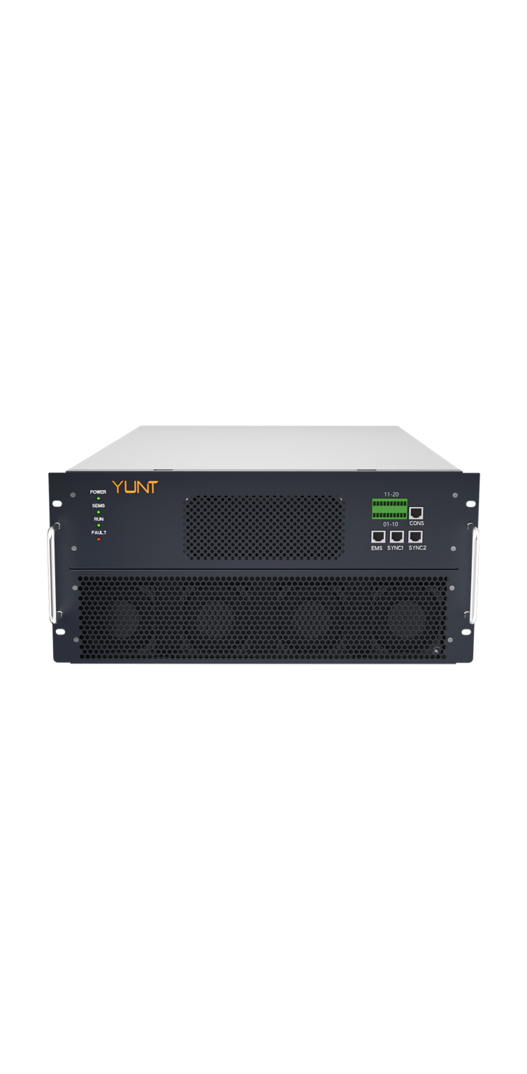
Field experience shows that small firmware or PCS configuration changes yield outsized improvements in THD at low load—so target the control layer first. For a practical partner that combines robust modules and firmware support, consider the solutions from YUNT. —