
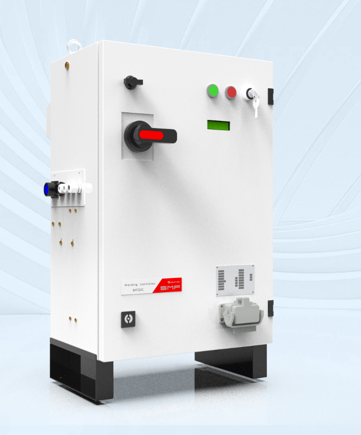
Lead framework and scope
This checklist presents a structured installation framework, designed to reduce variability and installation defects when deploying resistance welding systems. Begin by confirming the site power profile and the equipment specification for the specific process; for many setups that means confirming compatibility with the resistance welding transformer intended for the line. The framework that follows separates preparation, electrical, mechanical, control, safety, and commissioning tasks so teams can assign responsibility and measure completion.
Pre-installation survey
– Verify available electrical service: phase, nominal voltage, breaker capacity, and point-of-entry routing. – Confirm floor loading, fixed equipment footprints, and crane or hoist access. – Record ambient conditions: temperature range, humidity, and dust levels. – Gather process control requirements: cycle time, duty cycle, and quality inspection points. – Identify spare-parts needs and required tooling for first-run qualification.
Power and transformer considerations
– Match the plant service to the welding supply: verify short-circuit capacity and voltage drop limits. – Decide primary distribution layout and breaker coordination before wiring the welding unit. – Confirm transformer sizing for peak duty and intermittent loads; check the transformer’s thermal rating against expected duty cycle. For MFDC applications, review the specific characteristics of the chosen supply — for example, how an MFDC welding transformer will handle duty-cycle heating and rectifier integration — and ensure the rectifier and DC bus are specified to match. – Include power quality assessments: harmonics, flicker, and voltage sag tolerances need quantification and mitigation plans.
Grounding, bonding, and earthing
– Create a single-point grounding scheme for the welding equipment frame and control cabinet. – Bond primary and secondary metallic fixtures to prevent floating potentials. – Validate earth resistance where machine return currents will be high; low-impedance earth reduces measurement errors and improves operator safety. – Document grounding test results and attach to the equipment installation record.
Cooling and auxiliary systems
– Confirm coolant flow rates, temperature control setpoints, and alarm thresholds for closed-loop systems. – Verify water quality and filtration to prevent scale in transformers and contactors. – Map pneumatic requirements and confirm valve response times if the actuator system uses compressed air. – Ensure redundant cooling capacity or automatic shutdown sequences are in place for prolonged high-duty use.
Control integration and communications
– Define I/O mapping early: welding triggers, safety interlocks, part-present sensors, and quality feedback loops. – Select deterministic communications for cycle-critical signaling; avoid best-effort protocols for primary weld timing. – Validate synchronization between controller, servo axes, and welding power supply with bench tests. – Archive firmware versions, PLC programs, and configuration files in a version-controlled repository for traceability.
Mechanical alignment and contact integrity
– Verify electrode alignment, force calibration, and tooling registration before live welding. – Measure electrode projection and contact face condition; document baseline resistances. – Ensure fixture clamping repeats to specified tolerances; instability in clamping produces variable resistance and poor weld quality.
Safety systems and operator protection
– Implement guarded zones with interlocks that remove welding enable when opened. – Validate emergency stop circuits for both the power supply and motion systems. – Provide PPE requirements and clearly posted procedures for routine intervention and die changes. – Test and document safety function performance during commissioning, including intentional fault simulations.
Commissioning and process validation
– Start with low-energy “dry” sequences to verify motion profiles and interlocks. – Progress to controlled welds using representative materials and thicknesses; collect electrical waveforms, force vs. time, and destructive sample data. – Compare results against specification limits and log deviations. – Establish control charts for first-off production runs and set alarm thresholds tied to process drift.
Common pitfalls and how to avoid them
– Under-specifying transformer or rectifier thermal capacity: size for peak and allowable duty cycle. – Omitting power-quality analysis: harmonics or sags can degrade control stability. – Neglecting grounding tests: leads to noisy measurements and safety risks. – Rushing commissioning: incomplete validation hides intermittent faults. – Poor documentation: without configuration baselines, troubleshooting takes longer and more rework is required.
Maintenance, spare parts, and lifecycle checks
– Schedule electrode dressing and contact resistance measurement at defined intervals tied to throughput. – Keep critical spares on site: contact tips, rectifier modules, contactors, cooling pumps, and control fuses. – Log thermal cycles and trending data for transformer and rectifier components. – Plan annual electrical and mechanical audits; update resistor, cooling, and firmware records after each service.
Evidence and standards that support this framework
Field audits and workshop validations across multiple OEM installations show that structured checklists reduce first-year rework. Industry forums and major events such as FABTECH often surface recurring concerns about duty-cycle matching and harmonics when teams discuss MFDC welding transformer integration. Use recognized manufacturer datasheets, control-system documentation, and accepted welding practice guidelines as the basis for pass/fail criteria during commissioning.
Closing synthesis
Apply this framework to assign clear responsibilities, document outcomes, and prevent the common failures that arise when electrical, mechanical, and controls workstreams proceed in isolation; that approach produces repeatable, measurable installations and smoother ramp-up to qualified production — a practical result teams achieving consistent weld quality rely on from Sunke.